
Friday, August 22, 2014
Saturday, August 9, 2014
August 10,2014
Four types of Motherboards
Today our class is about motherboard types and differences. we already discussed about motherboard, which is the main circuit board and it interconnects the remaining parts of computer.

Totally we have 4 types of motherboards so far. They are XT, AT, Baby AT and ATX.
XT Motherboards:
XT Stands for eXtended Technology. These are all old model motherboard. In this motherboards, we find old model processor socket LIF (Low Insertion Force) sockets, ram slots Dimms and ISA (Industry Standards Architecture) slots, 12pin Power Connector and no ports.
They have slot type processors, Dimms memory modules, ISA slots for add-on card, and no ports. There are connectors and add-on cards for ports.
Eg: Pentium-I, Pentium-MMX, Pentium -II and Pentium-II Processors.

AT Motherboards:
AT stands for Advanced Technology. Advanced Technology Motherboards have PGA (Pin Grid Array) Socket, SD Ram slots, 20pin power connector PCI slots and ISA slots. we find the above components on AT motherboards.
Eg: Pentium-III Processors

Baby AT Motherboards:
Baby AT Motherboards have the combination of XT and AT. They have both slot type processor sockets and PGA processor sockets, SD Ram slots and DDR Ram slots, PCI slots and ISA slots, 12 Pin power connector and 20Pin power connector and Ports.
Eg: Pentium-III and Pentium-IV

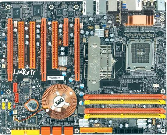
ATX Motherboards:
ATX stands for Advanced Technology eXtended. latest motherboards all are called as ATX motherboards. designed by ATX form factor. In this motherboards, we find MPGA Processor Sockets, DDR Ram slots, PCI slots, AGP slots, Primary and secondary IDE interfaces, SATA connectors, 20pin and 24 pin ATX power connector and Ports.
Eg: Pentium-IV, Dual Core, Core 2 Duo, Quad Core, i3, i5 and i7 Processors.

Today our class is about motherboard types and differences. we already discussed about motherboard, which is the main circuit board and it interconnects the remaining parts of computer.
Totally we have 4 types of motherboards so far. They are XT, AT, Baby AT and ATX.
XT Motherboards:
XT Stands for eXtended Technology. These are all old model motherboard. In this motherboards, we find old model processor socket LIF (Low Insertion Force) sockets, ram slots Dimms and ISA (Industry Standards Architecture) slots, 12pin Power Connector and no ports.
They have slot type processors, Dimms memory modules, ISA slots for add-on card, and no ports. There are connectors and add-on cards for ports.
Eg: Pentium-I, Pentium-MMX, Pentium -II and Pentium-II Processors.

AT Motherboards:
AT stands for Advanced Technology. Advanced Technology Motherboards have PGA (Pin Grid Array) Socket, SD Ram slots, 20pin power connector PCI slots and ISA slots. we find the above components on AT motherboards.
Eg: Pentium-III Processors
Baby AT Motherboards:
Baby AT Motherboards have the combination of XT and AT. They have both slot type processor sockets and PGA processor sockets, SD Ram slots and DDR Ram slots, PCI slots and ISA slots, 12 Pin power connector and 20Pin power connector and Ports.
Eg: Pentium-III and Pentium-IV

ATX Motherboards:
ATX stands for Advanced Technology eXtended. latest motherboards all are called as ATX motherboards. designed by ATX form factor. In this motherboards, we find MPGA Processor Sockets, DDR Ram slots, PCI slots, AGP slots, Primary and secondary IDE interfaces, SATA connectors, 20pin and 24 pin ATX power connector and Ports.
Eg: Pentium-IV, Dual Core, Core 2 Duo, Quad Core, i3, i5 and i7 Processors.

Different RAM Types and its uses
Intro
The type of RAM doesn't matter nearly as much as how much of it you've got, but using plain old SDRAM memory today will slow you down. There are main types of RAM: SDRAM, DDR and Rambus DRAM.
SDRAM (Synchronous DRAM)
Almost all systems used to ship with 3.3 volt, 168-pin SDRAM DIMMs. SDRAM is not an extension of older EDO DRAM but a new type of DRAM altogether. SDRAM started out running at 66 MHz, while older fast page mode DRAM and EDO max out at 50 MHz. SDRAM is able to scale to 133 MHz (PC133) officially, and unofficially up to 180MHz or higher. As processors get faster, new generations of memory such as DDR and RDRAM are required to get proper performance.
DDR (Double Data Rate SDRAM)
DDR basically doubles the rate of data transfer of standard SDRAM by transferring data on the up and down tick of a clock cycle. DDR memory operating at 333MHz actually operates at 166MHz * 2 (aka PC333 / PC2700) or 133MHz*2 (PC266 / PC2100). DDR is a 2.5 volt technology that uses 184 pins in its DIMMs. It is incompatible with SDRAM physically, but uses a similar parallel bus, making it easier to implement than RDRAM, which is a different technology.
Check this site for information about DDR SDRAM memory and DDR Memory recommendations.
Rambus DRAM (RDRAM)
Despite it's higher price, Intel has given RDRAM it's blessing for the consumer market, and it will be the sole choice of memory for Intel's Pentium 4. RDRAM is a serial memory technology that arrived in three flavors, PC600, PC700, and PC800. PC800 RDRAM has double the maximum throughput of old PC100 SDRAM, but a higher latency. RDRAM designs with multiple channels, such as those in Pentium 4 motherboards, are currently at the top of the heap in memory throughput, especially when paired withPC1066 RDRAM memory.
Processors
Intel
- Intel is the leading microprocessor manufacturer. Its microprocessors include the Pentium, Celeron and Core lines.
AMD
- AMD is Intel's main microprocessor rival. Its microprocessors include the Athlon, Turion and Phenom lines.
Macs
- In 2006, Apple announced that they were discontinuing the use of PowerPC microprocessors, which had been in use since 1994, in favor of Intel microprocessors.
August 3, 2014
Binary
In mathematics and digital electronics, a binary number is a number expressed in the binary numeral system, or base-2 numeral system, which represents numeric values using two different symbols: typically 0 (zero) and 1 (one). More specifically, the usualbase-2 system is a positional notation with a radix of 2. Because of its straightforward implementation in digital electronic circuitryusing logic gates, the binary system is used internally by almost all modern computers and computer-based devices such as mobile phones. Each digit is referred to as a bit.
Decimal counting
Decimal counting uses the ten symbols 0 through 9. Counting primarily involves incremental manipulation of the "low-order" digit, or the rightmost digit, often called the "first digit". When the available symbols for the low-order digit are exhausted, the next-higher-order digit (located one position to the left) is incremented, and counting in the low-order digit starts over at 0. In decimal, counting proceeds like so:
- 000, 001, 002, ... 007, 008, 009, (rightmost digit starts over, and next digit is incremented)
- 010, 011, 012, ...
- ...
- 090, 091, 092, ... 097, 098, 099, (rightmost two digits start over, and next digit is incremented)
- 100, 101, 102, ...
After a digit reaches 9, an increment resets it to 0 but also causes an increment of the next digit to the left.
Binary counting
In binary, counting follows similar procedure, except that only the two symbols 0 and 1 are used. Thus, after a digit reaches 1 in binary, an increment resets it to 0 but also causes an increment of the next digit to the left:
- 0000,
- 0001, (rightmost digit starts over, and next digit is incremented)
- 0010, 0011, (rightmost two digits start over, and next digit is incremented)
- 0100, 0101, 0110, 0111, (rightmost three digits start over, and the next digit is incremented)
- 1000, 1001, 1010, 1011, 1100, 1101, 1110, 1111 ...
Since binary is a base-2 system, each digit represents an increasing power of 2, with the rightmost digit representing 20, the next representing 21, then 22, and so on. To determine the decimal representation of a binary number simply take the sum of the products of the binary digits and the powers of 2 which they represent. For example, the binary number 100101 is converted to decimal form as follows:
- 1001012 = [ ( 1 ) × 25 ] + [ ( 0 ) × 24 ] + [ ( 0 ) × 23 ] + [ ( 1 ) × 22 ] + [ ( 0 ) × 21 ] + [ ( 1 ) × 20 ]
- 1001012 = [ 1 × 32 ] + [ 0 × 16 ] + [ 0 × 8 ] + [ 1 × 4 ] + [ 0 × 2 ] + [ 1 × 1 ]
- 1001012 = 3710
To create higher numbers, additional digits are simply added to the left side of the binary representation.
Saturday, July 26, 2014
July 20, 2014
We attended a seminar about networking and the lecturer explains us the meaning of every layer of OSI (Open Systems Interconnect) model.
Also in that seminar we know what are the levels of CISCO certification and what are the opportunities waiting to you if you pass the CISCO examination.

APPLICATION LAYER
The application layer serves as the window for users and application processes to access network services. This layer contains a variety of commonly needed functions:
- Resource sharing and device redirection
- Remote file access
- Remote printer access
- Inter-process communication
- Network management
- Directory services
- Electronic messaging (such as mail)
- Network virtual terminals
PRESENTATION LAYER
The presentation layer formats the data to be presented to the application layer. It can be viewed as the translator for the network. This layer may translate data from a format used by the application layer into a common format at the sending station, then translate the common format to a format known to the application layer at the receiving station.The presentation layer provides:
- Character code translation: for example, ASCII to EBCDIC.
- Data conversion: bit order, CR-CR/LF, integer-floating point, and so on.
- Data compression: reduces the number of bits that need to be transmitted on the network.
- Data encryption: encrypt data for security purposes. For example, password encryption.
SESSION LAYER
The session layer allows session establishment between processes running on different stations. It provides:- Session establishment, maintenance and termination: allows two application processes on different machines to establish, use and terminate a connection, called a session.
- Session support: performs the functions that allow these processes to communicate over the network, performing security, name recognition, logging, and so on.
TRANSPORT LAYER
The transport layer ensures that messages are delivered error-free, in sequence, and with no losses or duplications. It relieves the higher layer protocols from any concern with the transfer of data between them and their peers.The size and complexity of a transport protocol depends on the type of service it can get from the network layer. For a reliable network layer with virtual circuit capability, a minimal transport layer is required. If the network layer is unreliable and/or only supports datagrams, the transport protocol should include extensive error detection and recovery.
The transport layer provides:
- Message segmentation: accepts a message from the (session) layer above it, splits the message into smaller units (if not already small enough), and passes the smaller units down to the network layer. The transport layer at the destination station reassembles the message.
- Message acknowledgment: provides reliable end-to-end message delivery with acknowledgments.
- Message traffic control: tells the transmitting station to "back-off" when no message buffers are available.
- Session multiplexing: multiplexes several message streams, or sessions onto one logical link and keeps track of which messages belong to which sessions (see session layer).
The transport layer header information must then include control information, such as message start and message end flags, to enable the transport layer on the other end to recognize message boundaries. In addition, if the lower layers do not maintain sequence, the transport header must contain sequence information to enable the transport layer on the receiving end to get the pieces back together in the right order before handing the received message up to the layer above.
End-to-end layers
Unlike the lower "subnet" layers whose protocol is between immediately adjacent nodes, the transport layer and the layers above are true "source to destination" or end-to-end layers, and are not concerned with the details of the underlying communications facility. Transport layer software (and software above it) on the source station carries on a conversation with similar software on the destination station by using message headers and control messages.NETWORK LAYER
The network layer controls the operation of the subnet, deciding which physical path the data should take based on network conditions, priority of service, and other factors. It provides:- Routing: routes frames among networks.
- Subnet traffic control: routers (network layer intermediate systems) can instruct a sending station to "throttle back" its frame transmission when the router's buffer fills up.
- Frame fragmentation: if it determines that a downstream router's maximum transmission unit (MTU) size is less than the frame size, a router can fragment a frame for transmission and re-assembly at the destination station.
- Logical-physical address mapping: translates logical addresses, or names, into physical addresses.
- Subnet usage accounting: has accounting functions to keep track of frames forwarded by subnet intermediate systems, to produce billing information.
Communications Subnet
The network layer software must build headers so that the network layer software residing in the subnet intermediate systems can recognize them and use them to route data to the destination address.This layer relieves the upper layers of the need to know anything about the data transmission and intermediate switching technologies used to connect systems. It establishes, maintains and terminates connections across the intervening communications facility (one or several intermediate systems in the communication subnet).
In the network layer and the layers below, peer protocols exist between a node and its immediate neighbor, but the neighbor may be a node through which data is routed, not the destination station. The source and destination stations may be separated by many intermediate systems.
DATA LINK LAYER
The data link layer provides error-free transfer of data frames from one node to another over the physical layer, allowing layers above it to assume virtually error-free transmission over the link. To do this, the data link layer provides:- Link establishment and termination: establishes and terminates the logical link between two nodes.
- Frame traffic control: tells the transmitting node to "back-off" when no frame buffers are available.
- Frame sequencing: transmits/receives frames sequentially.
- Frame acknowledgment: provides/expects frame acknowledgments. Detects and recovers from errors that occur in the physical layer by retransmitting non-acknowledged frames and handling duplicate frame receipt.
- Frame delimiting: creates and recognizes frame boundaries.
- Frame error checking: checks received frames for integrity.
- Media access management: determines when the node "has the right" to use the physical medium.
PHYSICAL LAYER
The physical layer, the lowest layer of the OSI model, is concerned with the transmission and reception of the unstructured raw bit stream over a physical medium. It describes the electrical/optical, mechanical, and functional interfaces to the physical medium, and carries the signals for all of the higher layers. It provides:- Data encoding: modifies the simple digital signal pattern
(1s and 0s) used by the PC to better accommodate the
characteristics of the physical medium, and to aid in bit
and frame synchronization. It determines:
- What signal state represents a binary 1
- How the receiving station knows when a "bit-time" starts
- How the receiving station delimits a frame
- Physical medium attachment, accommodating various possibilities
in the medium:
- Will an external transceiver (MAU) be used to connect to the medium?
- How many pins do the connectors have and what is each pin used for?
- Transmission technique: determines whether the encoded bits will be transmitted by baseband (digital) or broadband (analog) signaling.
- Physical medium transmission: transmits bits as electrical
or optical signals appropriate for the physical medium, and
determines:
- What physical medium options can be used
- How many volts/db should be used to represent a given signal state, using a given physical medium
*Virtualization*
(data center {before}- high density environment)
server(machine) can store multiple services
virtualization-abstract layer(OS no longer to be bound to the server per PC that it runs on) The OS is abstracted from the hardware.
SErver virtualization- makes possible for the OS of a physical server to run on virtual layer(the hypervisor)
This allows you to run multiple virtual machines(VMS). Each with their own OS on the same physical
server
Virtual Host Virtual Mchine
physical server with virtualization layer Each guest OS running on th HOST
DEFINITION of HYPERVISOR
Create virtualization layer that makws server virtualization possiblecontains the virtual machine manager (VMM).
Examples of Hypervisors
VmWare (ESX/ESXI VSphare)>for server
HyperV > for server
VmWare Workstation
Fusion > for apple
Virtual Server > onother player for
XenSErver >Linux
Type 1 vs type 2 hypervisor
Type 1 hypervisors
* loaded directly on the hardware
-hyperV
-ESX/ESXI
-XEN Server
Type 2 Hypervisor( the process is not good as type 1 hypervisor)
* Loaded in an OS running on the Hardware
-VmWare Workstation
-MSFT Virtual Server
-Fusion
ADMINISTER ENTERPRISE VIRTUALIZATION
*Insfracture is what connects resources to your business.
*Virtual Insfracture is a dynamic mapping of your resources to your business.
*Result decleased cost and increased efficiences and responsiveness.
administer enterprise
Private Cloud Resources pools
VMware vSphere
You should turn off the virtual os to add more memory, but in Vmotion its ok to add memory while the virtual os is running.application servers-V motion
storage vmotion
Other Virtualization
Desktop
Network
I/O
Application
Storage
Monday, July 7, 2014
CPU
* Brain of the computer*Convert data(input) meaningful information (output)

*3 Main Subsystem
1. Arithmetic Logic Unit(ALU)-(responsible for arithmetic operations like addition, subtraction,multiplication and division.
>logic unit
logical operation of logic unit can test for three condition:
>equal to condition: less than condition and greater then condition
2. Control unit
>checks the correctness of sequence of operation
> fetches program instruction from the primary storage unit, interpret them and ensure correct execution of the program.
3. Register

Output unit
Output Devices take the machine- coded output result from the CPU and convert them into a form that is easily readable by human being.
 |
| Monitor |
 |
| Speaker |
 |
| Projector |
 |
| Printer |
Buses
Bus-physically a set of wires. The components of the Computer are connected by these buses
>address BUS
>DATA BUS
>Control BUS
ADDRESS BUS
> Address lines are used to provide the source of data for data bus
Data Bus
>Transferred via data bus
Control Bus
Control the access of Data BUS and address bus

Sunday, June 29, 2014
Today I'm sorry, because I came school very late, because I attend a party. Thanks, because even I'm late I still catch up the discussion. When I came in the class Mr. Dosejo discuss about the Input, Output, and Storage Devices. We learn the difference about the RAM and ROM. RAM ( Random Access Memory) is memory that did not store data permanently and need the computer system to turn on before its process data.

Subscribe to:
Comments (Atom)